SDR Local Oscillator
A discrete quadrature ring oscillator characterized across frequency, supply noise, interference, and FLL-control experiments.
Overview
This local-oscillator experiment used a direct-quadrature ring topology built from discrete components. I characterized its tuning range and jitter, compared its spectrum with an Si5351 clock generator, and explored a frequency-locked-loop control path.
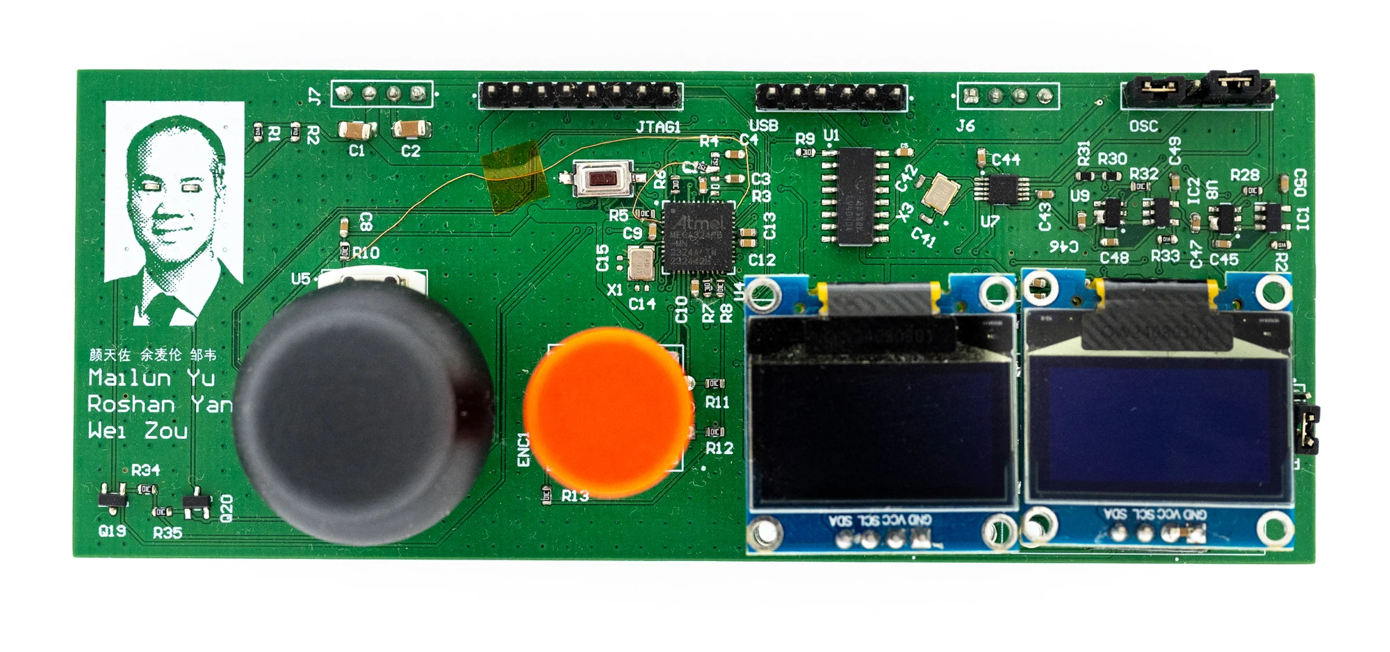
The assembled SDR local-oscillator board.
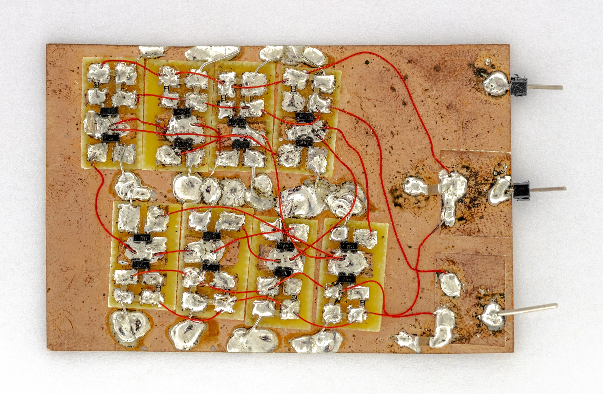
The discrete ring-oscillator prototype.
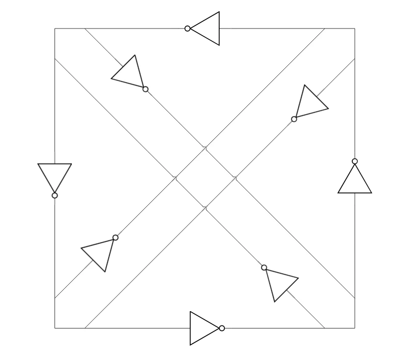
The direct-quadrature topology used for the oscillator.
Frequency range and spectral behavior
The oscillator operated from roughly 4 kHz at the low end to about 22.5 MHz at the high end.
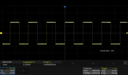
Low-frequency operation at approximately 4 kHz.
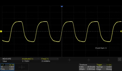
High-frequency operation at approximately 22.5 MHz.
The discrete oscillator showed visible jitter. For comparison, the Si5351 produced a much cleaner spectrum.
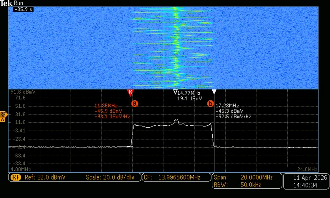
Jitter observed on the discrete oscillator.
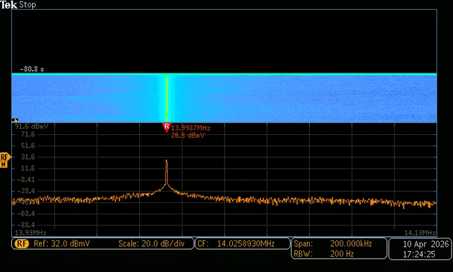
Si5351 spectrum used as a comparison.
Interference and control experiments
OLED activity coupled noise into the oscillator supply. With the displays enabled the output became erratic; disabling them removed much of the disturbance.
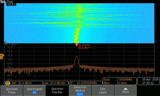
The effect of display-related power-supply noise.
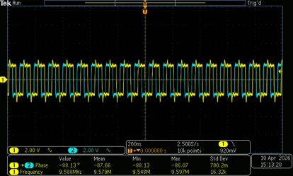
Waveform without the interfering activity.
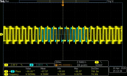
Waveform with interference present.
I also tested an FLL control voltage, but the oscillator’s jitter made stable control difficult.
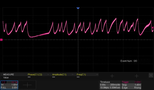
FLL control-voltage behavior during the experiment.
PWM filtering
The likely cause of the jitter was the ESL of the filter capacitors on the PWM, which would cause spikes to remain on the drive voltage of the VCO. The effect of this is the pulses frequency modulate the oscillator, which also explains the jitter of the frequency, having stable periods and limited excursion.
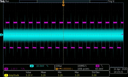
PWM and filtered waveforms.
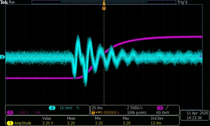
An ESL-related pulse on the filtered PWM waveform.