All projects

Project · 2026

RF · VCO · Microwave

C-Band Negative Resistance VCO

A compact C-band negative-resistance voltage-controlled oscillator.

Overview

A negative resistance oscillator I designed for an ISM band radar project I’m currently working on.
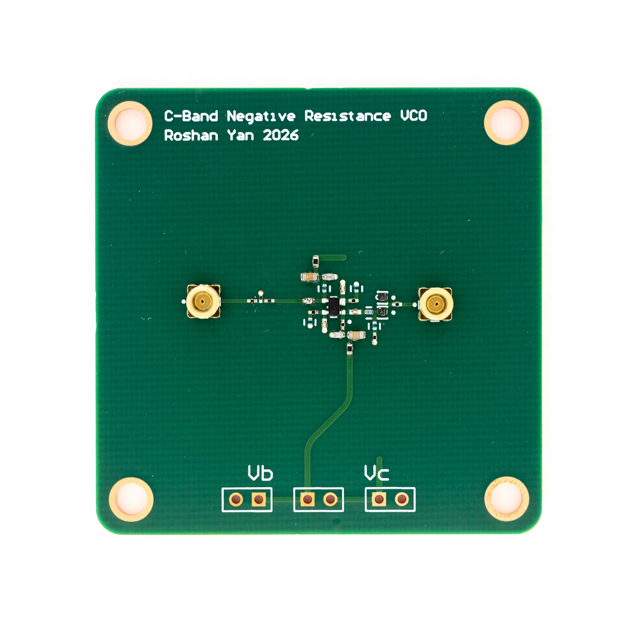
A square green PCB for a C-band negative-resistance voltage-controlled oscillator.

The assembled C-band VCO prototype.

Circuit design
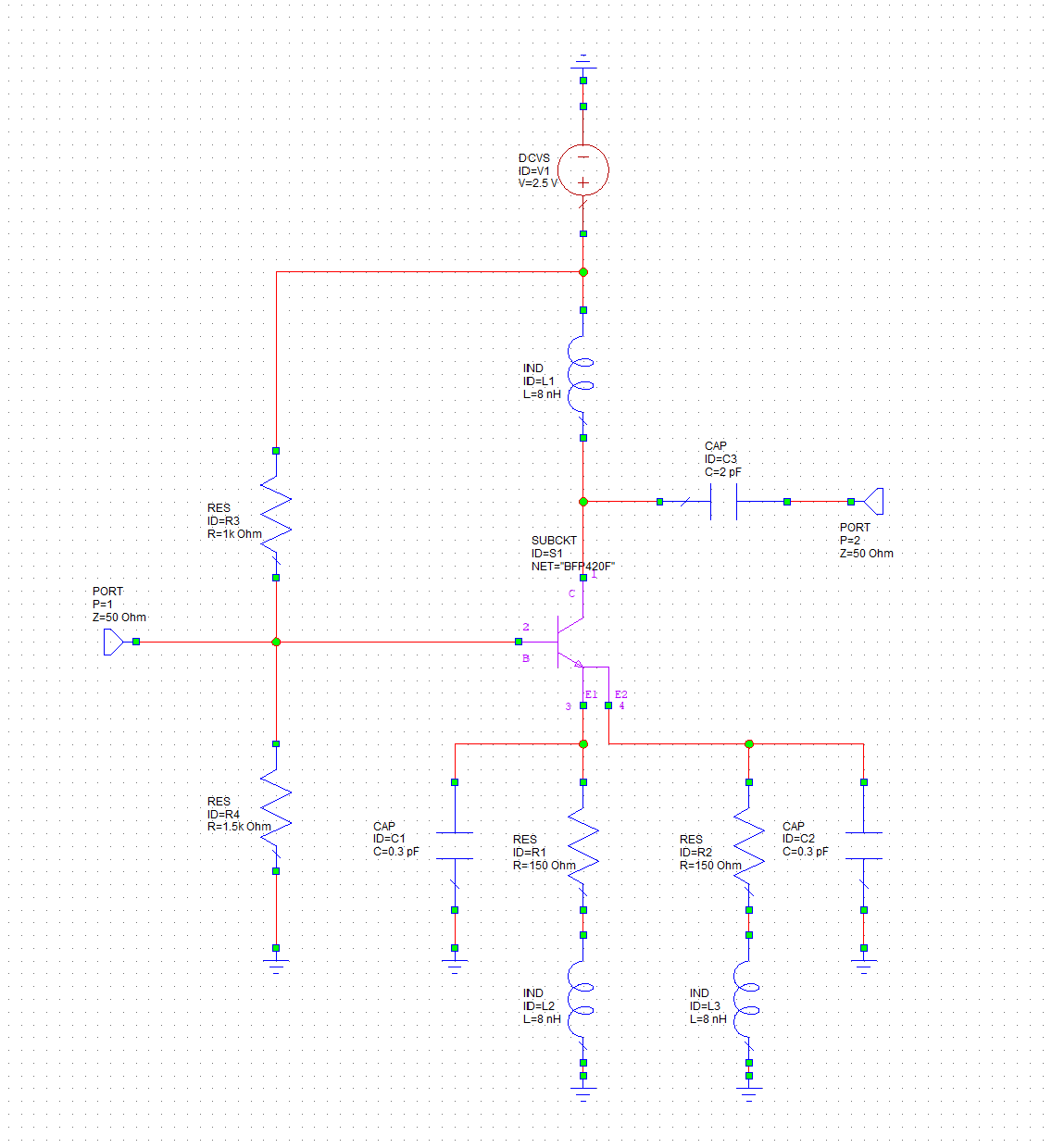
Negative-resistance amplifier schematic using a BFP420F transistor.

Negative-resistance amplifier stage.

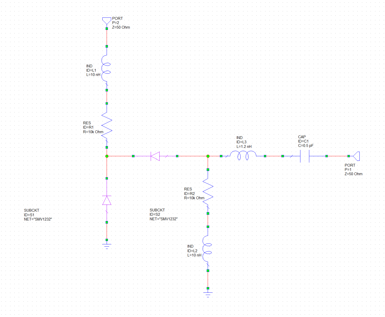
Varactor tuning and output network schematic.

Varactor tuned tank network.

Simulation
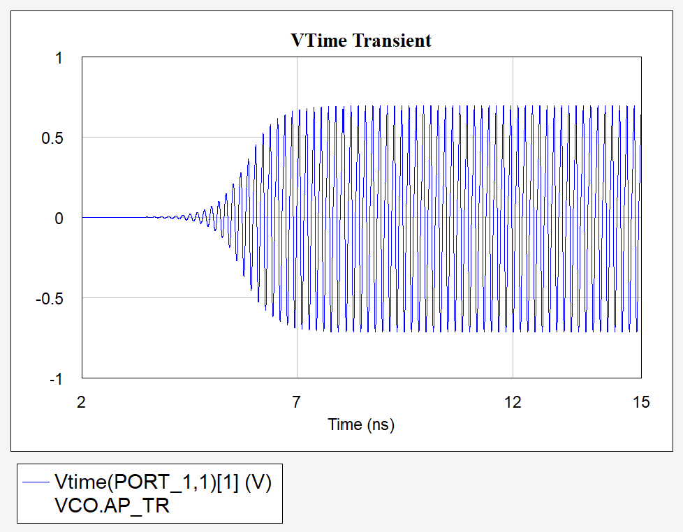
Transient simulation showing the oscillator starting and settling to a steady amplitude.

Simulated oscillator startup.

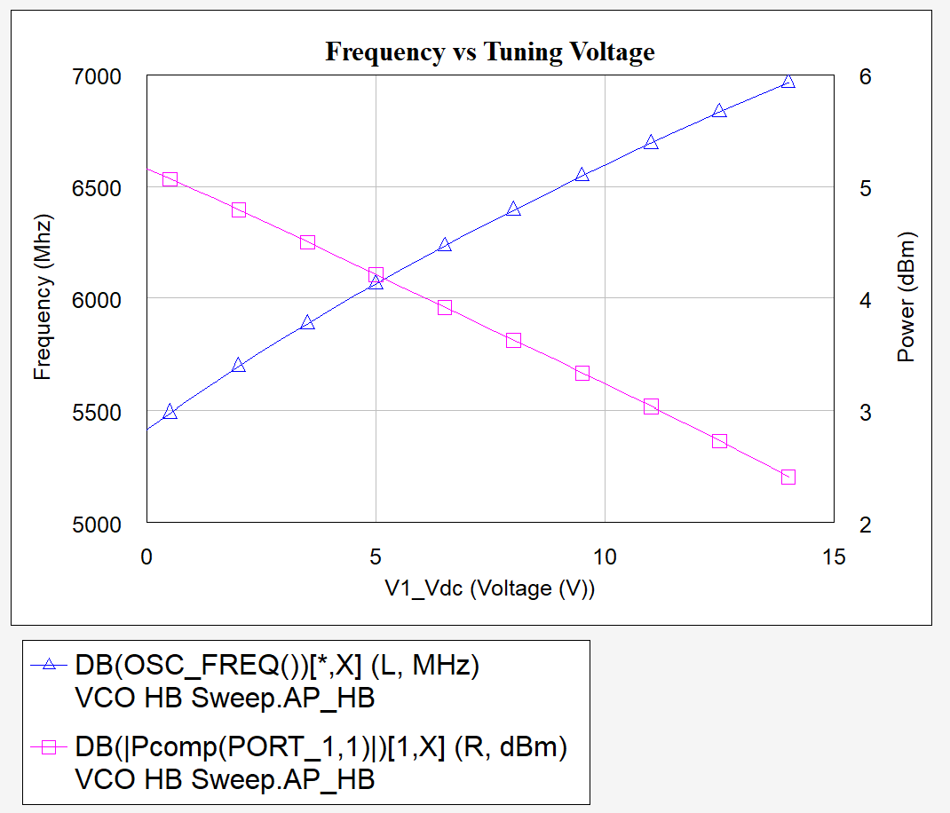
Simulated oscillator frequency and output power plotted against tuning voltage.

Frequency and output power versus tuning voltage.
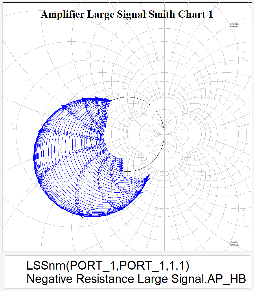
Large-signal negative-resistance sweep on a Smith chart.

Large-signal negative-resistance sweep.
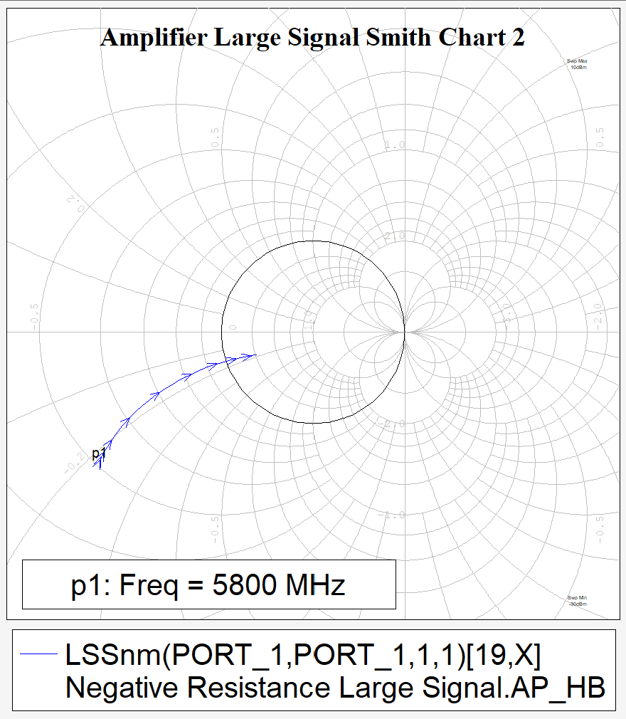
Large-signal Smith chart with the 5.8 GHz point marked.

Load line at 5.8GHz, the final operating point would be just outside the edge of the Smith chart.

Bench measurement
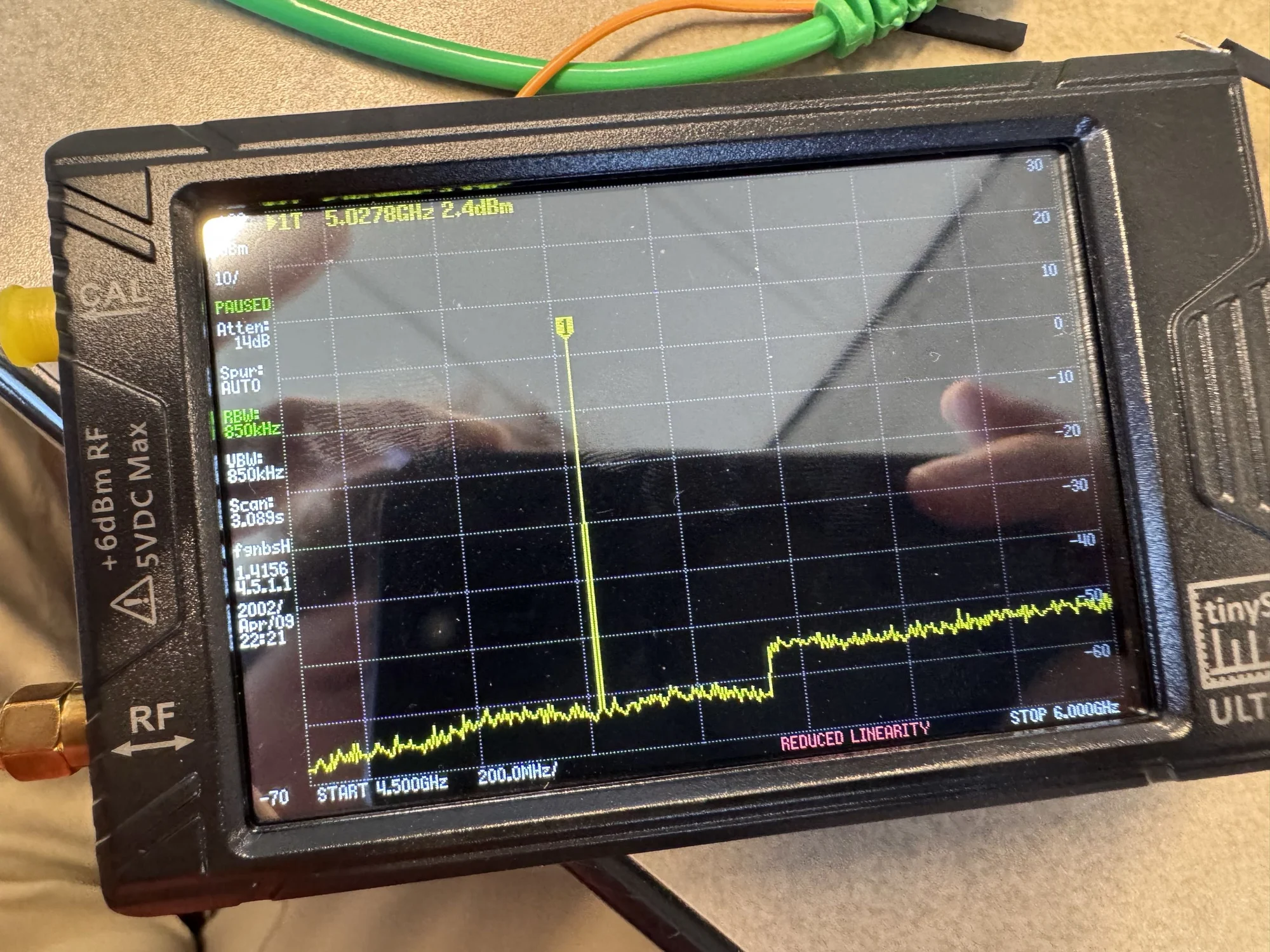
Spectrum-analyzer measurement of the C-band VCO output at 5.0278 GHz and 2.4 dBm.

Measured output at 5.0278 GHz and 2.4 dBm.